
TPS7A4525EVM-385
EVALUATION MOD 385 FOR TPS7A4525
This user’s guide describes the characteristics, operation, and use of the TPS7A45xxEVM-385 evaluation
module (EVM). This EVM demonstrates the Texas Instruments TPS7A45xx low-noise
fast-transient-response 1.5-A low-dropout (LDO) voltage regulator. This user’s guide includes setup
instructions, a schematic diagram, a bill of materials (BOM), and PCB layout drawings for the EVM.
1 Introduction
The TPS7A45xxEVM-385 helps designers evaluate the operation and performance of the TPS7A45xx dc/dc converter. This converter is a 1.5-A low-noise fast-transient-response regulator.
1.1 Related Documentation From Texas Instruments
TPS7A45xx 1.5-A Low-Noise Fast-Transient-Response Low-Dropout Regulator in 5DDPAK/TO-263 package data sheet (SLVS720 )
2 Setup
This section describes the jumpers and connectors on the EVM and how to properly connect, set up, and use the TPS7A45xxEVM-385.
2.1 Input/Output Connector Descriptions
2.1.1 J1– INPUT (4-Wire Power/Sense Option)
This is the positive input supply voltage. Twist the leads to the input supply and keep them as short as possible to minimize EMI transmission.
2.1.2 J3– IN_GND (4-Wire Power/Sense Option)
This is the return connection for the input power supply of the converter.
2.1.3 J2– OUTPUT (4-Wire Power/Sense Option)
This is the positive connection from the output. Connect this pin to the positive input of the load.
2.1.4 J4– OUT_GND (4-Wire Power/Sense Option)
This is the return connection for the output.
2.1.5 JP1–ENABLE
This jumper enables or disables the regulator. Connecting the shorting jumper between pins 1 and 2 (VIN and EN) enables the converter. Connecting the shorting jumper between pins 2 and 3 (EN and GND) disables the converter. Do not leave this pin floating.
2.1.6 JP2– MODE
This jumper sets the mode of the TPS7A45xx. Connecting the shorting jumper between pins 1 and 2 forces the TPS7A45xx into fixed-output mode. Use this setting with fixed-output devices only. Remove J8 shorting jumper for adjustable-output devices.
For adjustable-output devices, the output voltage may be selected using these equations: VOUT = 1.21 (1 + R2 / R1) + IADJ · R2 IADJ = 1.21 / R1 R1 < 4.17 kW
3 Operation
Connect the positive input power supply to J1. Connect the input power return (ground) to J3. The TPS7A45xx device has an absolute maximum input voltage of 20 V. The recommended maximum operating voltage is 20 V.
Connect the desired load between J2 and J4. The TPS7A45xx device can supply up to 1.5 A of output current.
Configure jumpers JP1 and JP2 as required. The functions of JP1 and JP2 are described in Section 2.1.5 and Section 2.1.6, respectively.
4 Test Results
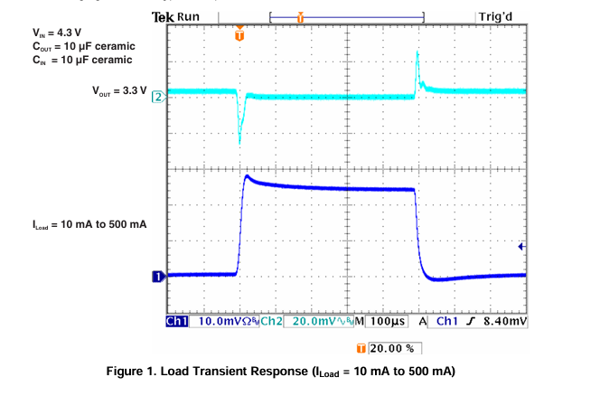
The following figures show typical responses of the TPS7A45xx to line and load transients.
- 苏州杭晶电子入驻工之芯商城,成为优质供应商
- TPS7A30-49EVM-567_TI(德州仪器)中文资料_英文资料_价格_PDF手册
- TLA2024EVM-PDK_TI(德州仪器)中文资料_英文资料_价格_PDF手册
- INA229_239EVM_TI(德州仪器)中文资料_英文资料_价格_PDF手册
- DAC8832EVM-PDK _TI(德州仪器)中文资料_英文资料_价格_PDF手册
- LP8557IEVM_TI(德州仪器)中文资料_英文资料_价格_PDF手册
- LAUNCHXL-F28027F TI(德州仪器)中文资料_英文资料_价格_PDF手册
- DLPDLCR160CPEVM DLP160CP TI(德州仪器)中文资料_英文资料_价格_PDF手册
- THS4631DDAEVM TI(德州仪器)中文资料_英文资料_价格_PDF手册
- DAC3482EVM TI(德州仪器)中文资料_英文资料_价格_PDF手册
- THS4302EVM TI(德州仪器)中文资料_英文资料_价格_PDF手册
- ADS7038Q1EVM-PDK_TI(德州仪器)中文资料_英文资料_价格_PDF手册
- LM3450AEV230V30/NOPB_TI(德州仪器)中文资料_英文资料_价格_PDF手册
- TPS72728DSEEVM-406_TI(德州仪器)中文资料_英文资料_价格_PDF手册
- WL1835MODCOM8A_TI(德州仪器)中文资料_英文资料_价格_PDF手册
 工商网监