
ADC3424EVM
Thisdocument isauser’sguidefor theADC3xxxEVMandADC3xJxxEVM.TheEVMsprovideaplatform forevaluatingtheADC3xxxandADC3xJxx.TheADC3xxxisadual-channelorquad-channel,12-bitor14 bit, serial LVDS interfaceanalog-to-digital converter (ADC). TheADC3xxxcomeswithsamplingspeed gradesof 25MSPS, 50MSPS, 80MSPS, and125MSPS.TheADC3xJxx isadual-channel orquad channel,12-bitor14-bit,JESD204B-compliant interfaceADC.TheADC3xJxxcomeswithsamplingspeed gradesof 50MSPS, 80MSPS, 125MSPS, and160MSPS. This familyof converters requiresonlya single1.8-Vsupply,providesflexibleinputclockdividers,andprovides internal featuresfor improved1/f (ADC32xx,ADC34xx) andSFDRperformance. Throughout thisdocument, theabbreviationsEVMand ADC3xxxx,andthetermevaluationmodulearesynonymouswiththeADC3xxxEVMandADC3xJxxEVM, unlessotherwisenoted.
1 EVM Block Diagram
Figure 1 and Figure 2 show simplified block diagrams of the default configuration of the EVM. The two or four analog inputs are supplied to the EVM through a single-ended SMA connection, then transformer coupled to turn the single-ended signal into a balanced differential signal, and then input to the ADC32xxx or ADC34xxx. A dual transformer input circuit is used for better phase and amplitude balance of the input signal than is typically produced by a single transformer input circuit.
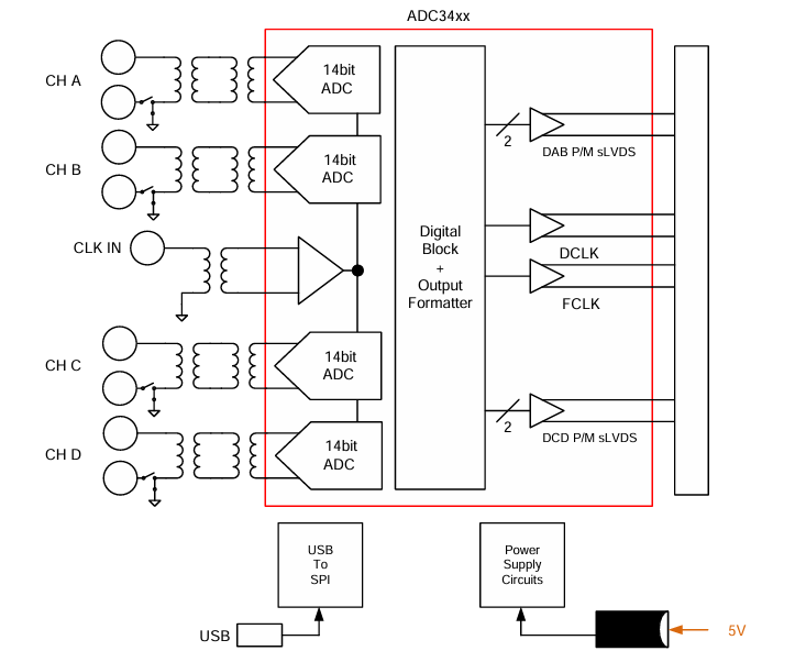
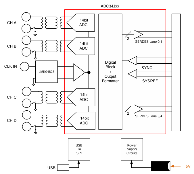
Theclockinput issuppliedbywayofasingle-endedsignal toanSMAconnector,andtransformercoupled toproduceadifferentialclocksignal fortheADC32/34xxEVM.FortheADC32J/34JxxEVM, theclock inputcanbegeneratedonboardusingtheLMK04828.
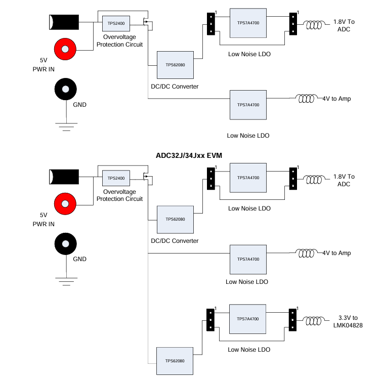
PowertotheADC3xxxEVMistypicallysuppliedfroma5-Vbenchsupplyusingtheonboardbarrel connectorandtheprovidedcable,orfromanappropriate5-V,3-Aminimumpowerbrick.Allnecessary voltagesfortheADCEVMarederivedfromthe5-Vinputconnection.
1.2 EVMPowerSupply
Figure3illustratesthepowersupplyoptionsavailableontheADC3xxxEVM.Jumpersareusedtochoose thepower-supplyoptions,withthedefault jumperpositionsindicatedbythedarkerportionof thejumper thatrepresentsthepresenceof thejumper.SeeTable2for jumperandfeedbackresistorconfiguration.
1.3 EVM Connectors and Jumpers
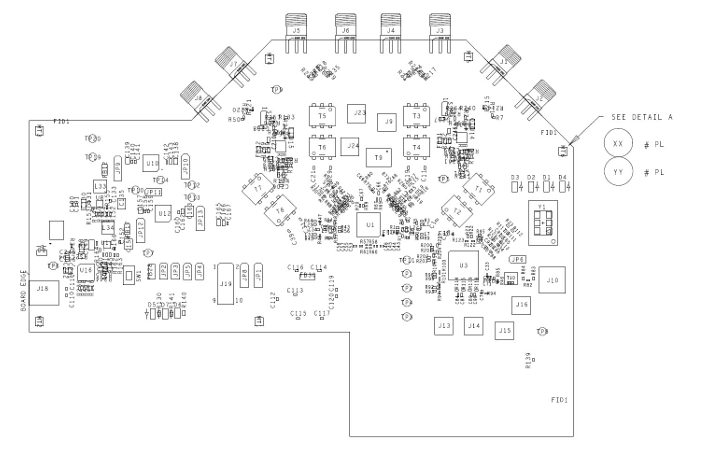 Figure 4 and Figure 5 show the locations of the connectors, jumpers, pushbutton switches, and LEDs.
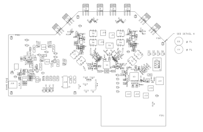
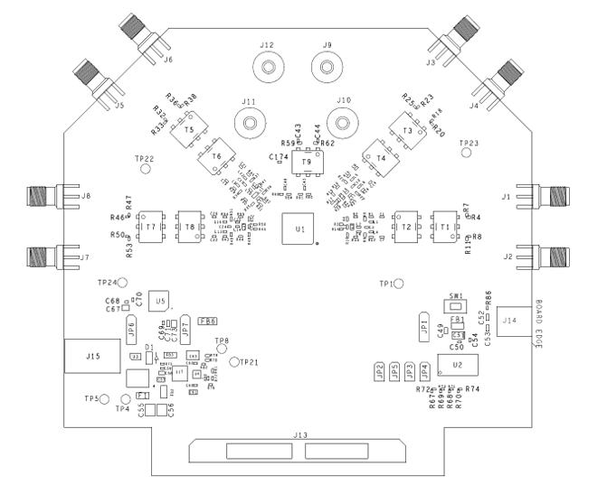
The EVM has a barrel connector for 5-V power. The SMA connectors connect the ADC input and ADC clock input to the ADC. Typically, the ADC inputs are transformer-coupled to accept single-ended connections. The input circuit can be configured to connect to two SMA connectors for differential signaling, if desired. Table 3 lists the connector information for the ADC3xxxx.
- 苏州杭晶电子入驻工之芯商城,成为优质供应商
- TPS7A30-49EVM-567_TI(德州仪器)中文资料_英文资料_价格_PDF手册
- TLA2024EVM-PDK_TI(德州仪器)中文资料_英文资料_价格_PDF手册
- INA229_239EVM_TI(德州仪器)中文资料_英文资料_价格_PDF手册
- DAC8832EVM-PDK _TI(德州仪器)中文资料_英文资料_价格_PDF手册
- LP8557IEVM_TI(德州仪器)中文资料_英文资料_价格_PDF手册
- LAUNCHXL-F28027F TI(德州仪器)中文资料_英文资料_价格_PDF手册
- DLPDLCR160CPEVM DLP160CP TI(德州仪器)中文资料_英文资料_价格_PDF手册
- THS4631DDAEVM TI(德州仪器)中文资料_英文资料_价格_PDF手册
- DAC3482EVM TI(德州仪器)中文资料_英文资料_价格_PDF手册
- THS4302EVM TI(德州仪器)中文资料_英文资料_价格_PDF手册
- ADS7038Q1EVM-PDK_TI(德州仪器)中文资料_英文资料_价格_PDF手册
- LM3450AEV230V30/NOPB_TI(德州仪器)中文资料_英文资料_价格_PDF手册
- TPS72728DSEEVM-406_TI(德州仪器)中文资料_英文资料_价格_PDF手册
- WL1835MODCOM8A_TI(德州仪器)中文资料_英文资料_价格_PDF手册
 工商网监