
LEDMCUEVM-132
MSP432E401Y MCU COMMUNICATION BD
This user's guide describes the specifications, board connection description, characteristics, operation, and use of the LEDMCUEVM-132 that uses the MSP432™ to control specific LED evaluation modules (EVMs). A complete schematic diagram, printed circuit board layouts, and bill of materials are included in this document.
1 Description
This user's guide describes the specifications, board connection description, characteristics, operation, and use of the LEDMCUEVM-132 MCU LED controller evaluation module (EVM). The LEDMCUEVM-132 implements SPI communications that support multiple devices on the bus, UART communications for the LMMs family of devices, CAN transceiver for UART to control LMM family of devices, 4 PWM signals for dimming, multiple IOs, isolated 5-V supply, digital isolators, and a standard CAN bus with a transciever. A complete schematic diagram, printed-circuit board layouts, and bill of materials are included in this document.
1.1 Typical Applications
This document outlines the operation and implementation of the LEDMCUEVM-132 as LED MCU controller board that communicates and controls other EVMs in the automotive LED driver and matrix managers.
1.2 Connector Description
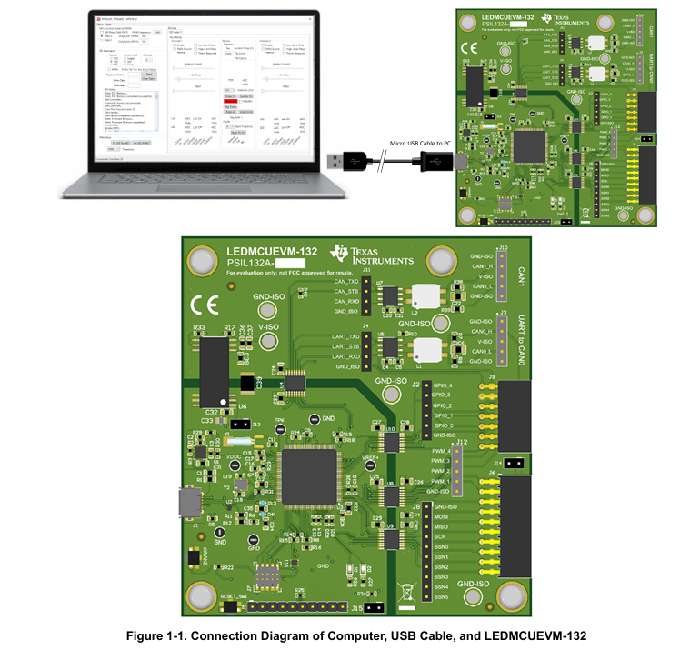
Table 1-1 describes the connectors and Table 1-2 lists the test points on the EVM and how to properly connect, set up, and use the LEDMCUEVM-132. Figure 1-1 shows the connection diagram and the default jumper locations of the LEDMCUEVM-132.
2 Features and Specifications
The LEDMCUEVM-132 provides a host of features that allow it to be used with a variety of EVMs and for the easy evaluation and debug of devices and systems.
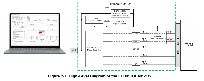
• A SPI bus that supports up to six devices is provided and is accessed via J6, J9, and J12 connectors. It comes from the MCU (MSP432E401Y) through a digital isolator to the connectors. J12 can be used with debug probes or can be mated to a connector that uses a standard 100-mil header.
• There are two pairs of PWM signals (PWM1 + PWM2 and PWM3 + PWM4) that can be used for PWM dimming of supported devices. These signals support up to 4 kHz operation and have the ability to be phase shifted by 180 degrees. J12 is a standard 100-mil head that can either be used for probing or to mate with a standard 100-mil connector.
• Five GPIOs are provided and depending on the EVM selection the GPIOs are either enabled or disabled. See the user's guide of the EVM for more details.
• The MCU generates UART commands that are used by the TPS92662 lighting matrix manager device. The single-ended communication is passed through a digital isolator and into a CAN transceiver to generate a differential signal that is commonly used in noisy environments. Either the single-ended UART signals are available via J4 header or the differential CAN signals are available by header J3.
• There is an isolated 5-V supply that is created from the USB bus (5 V) and is supplied to the secondary side to power the digital isolators, CAN transceivers, and is passed on to other EVMs as V-ISO. Not all EVMs use this supply. Some have their own supplies separated from the LEDMCUEVM-133.
• The LEDMCUEVM-133 supports firmware updates by the USB connection to the PC.
• If the customer wants to develop their own firmware for the MSP432E401Y, then they have that ability to do that by using J7 and the XDIS110 JTAG Debug Probe.
• The MSP432E401Y can also be connected to the Emulator connections of an external MSP-EXP432E401Y LaunchPad using J5.
• The LEDMCUEVM-132 has a connection to the CAN bus of the MSP432 and it is also attached to a CAN transceiver to generate a CAN signal. This hardware is not yet supported by the GUI.
3 Schematic, PCB Layout, and Bill of Materials
This section contains the LEDMCUEVM-132 schematics, PCB layouts, and bill of materials (BOM).
3.1 Schematic
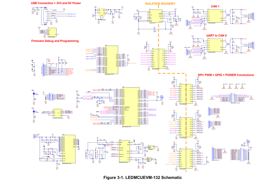
Figure 3-1 illustrates the LEDMCUEVM-132 schematic.
3.2 Layout
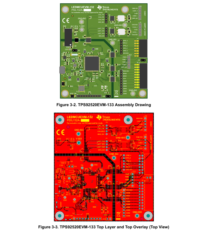
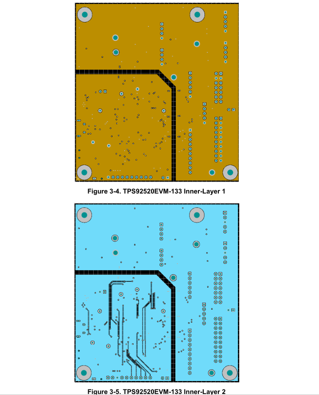
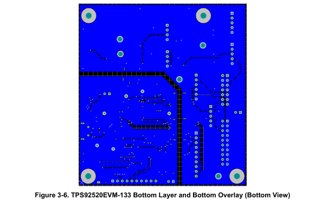
The LEDMCUEVM-132 is a 4-layer board. Figure 3-2, Figure 3-3, Figure 3-4, Figure 3-5, and Figure 3-6 illustrate the assembly, top, inner-layer1, inner-layer2, and the bottom side of the LEDMCUEVM-132 PCB layout. The Inner-layer 1 is a ground plane and there is no routing on this layer.
- 苏州杭晶电子入驻工之芯商城,成为优质供应商
- TPS7A30-49EVM-567_TI(德州仪器)中文资料_英文资料_价格_PDF手册
- TLA2024EVM-PDK_TI(德州仪器)中文资料_英文资料_价格_PDF手册
- INA229_239EVM_TI(德州仪器)中文资料_英文资料_价格_PDF手册
- DAC8832EVM-PDK _TI(德州仪器)中文资料_英文资料_价格_PDF手册
- LP8557IEVM_TI(德州仪器)中文资料_英文资料_价格_PDF手册
- LAUNCHXL-F28027F TI(德州仪器)中文资料_英文资料_价格_PDF手册
- DLPDLCR160CPEVM DLP160CP TI(德州仪器)中文资料_英文资料_价格_PDF手册
- THS4631DDAEVM TI(德州仪器)中文资料_英文资料_价格_PDF手册
- DAC3482EVM TI(德州仪器)中文资料_英文资料_价格_PDF手册
- THS4302EVM TI(德州仪器)中文资料_英文资料_价格_PDF手册
- ADS7038Q1EVM-PDK_TI(德州仪器)中文资料_英文资料_价格_PDF手册
- LM3450AEV230V30/NOPB_TI(德州仪器)中文资料_英文资料_价格_PDF手册
- TPS72728DSEEVM-406_TI(德州仪器)中文资料_英文资料_价格_PDF手册
- WL1835MODCOM8A_TI(德州仪器)中文资料_英文资料_价格_PDF手册
 工商网监
工商网监